Microbit Read/Write Pins
The pins are your board’s way to communicate with external devices connected to it. There are 19 pins for your disposal, numbered 0-16 and 19-20. Pins 17 and 18 are not available.
Three types of pins
There are three kinds of pins, differing in what is available for them.
- Analog. Return or set to floating numbers.
- Digital. Return or set to either 0 or 1.
- Touch. Return true or false
This table summarises the pins available, their types and what they are internally connected to. The pins are available as attributes on the microbit module: microbit.pin0 – microbit.pin20.
| Pin | Type | Function | Function V2 |
|---|---|---|---|
| 0 | Touch | Pad 0 | Pad 0 |
| 1 | Touch | Pad 1 | Pad 1 |
| 2 | Touch | Pad 2 | Pad 2 |
| 3 | Analog | Column 1 | Column 3 |
| 4 | Analog | Column 2 | Column 1 |
| 5 | Digital | Button A | Button A |
| 6 | Digital | Column 9 | Column 4 |
| 7 | Digital | Column 8 | Column 2 |
| 8 | Digital | ||
| 9 | Digital | Column 7 | |
| 10 | Analog | Column 3 | Column 5 |
| 11 | Digital | Button B | Button B |
| 12 | Digital | ||
| 13 | Digital | SPI SCK | SPI SCK |
| 14 | Digital | SPI MISO | SPI MISO |
| 15 | Digital | SPI MOSI | SPI MOSI |
| 16 | Digital | ||
| 19 | Digital | I2C SCL | I2C SCL |
| 20 | Digital | I2C SDA | I2C SDA |
The latest micro:bit device V2 has two additional pins that you can access in MicroPython, but that are not available via the edge connector:
They are represented by the classes listed below. Note that they form a hierarchy, so that each class has all the functionality of the previous class, and adds its own to that.
Note
Those classes are not actually available for the user, you can’t create new instances of them. You can only use the instances already provided, representing the physical pins on your board.
class microbit.MicroBitDigitalPin
read_digital()
Return 1 if the pin is high, and 0 if it’s low.write_digital(value)
Set the pin to high if value is 1, or to low, if it is 0.
class microbit.MicroBitAnalogDigitalPin
read_analog()
Read the voltage applied to the pin, and return it as an integer between 0 (meaning 0V) and 1023 (meaning 3.3V).write_analog(value)
Output a PWM signal on the pin, with the duty cycle proportional to the provided value. The value may be either an integer or a floating point number between 0 (0% duty cycle) and 1023 (100% duty).set_analog_period(period)
Set the period of the PWM signal being output to period in milliseconds. The minimum valid value is 1ms.set_analog_period_microseconds(period)
Set the period of the PWM signal being output to period in microseconds. The minimum valid value is 256µs.class microbit.MicroBitAnalogDigitalPinread_analog()
Read the voltage applied to the pin, and return it as an integer between 0 (meaning 0V) and 1023 (meaning 3.3V).
class microbit.MicroBitTouchPin
is_touched()
Return True if the pin is being touched with a finger, otherwise return False.
Note
The default touch mode for the pins on the edge connector is resistive. The default for the logo pin V2 is capacitive.
Resistive touch This test is done by measuring how much resistance there is between the pin and ground. A low resistance gives a reading of True. To get a reliable reading using a finger you may need to touch the ground pin with another part of your body, for example your other hand.
Capacitive touch This test is done by interacting with the electric field of a capacitor using a finger as a conductor. Capacitive touch does not require you to make a ground connection as part of a circuit.set_touch_mode(value)
Note
The default touch mode for the pins on the edge connector is resistive. The default for the logo pin V2 is capacitive.
Set the touch mode for the given pin. Value can be either CAPACITIVE or RESISTIVE. For example, pin0.set_touch_mode(pin0.CAPACITIVE).
The pull mode for a pin is automatically configured when the pin changes to an input mode. Input modes are when you call read_analog / read_digital / is_touched. The default pull mode for these is, respectively, NO_PULL, PULL_DOWN, PULL_UP. Calling set_pull will configure the pin to be in read_digital mode with the given pull mode.
Read Pins
For example, the script below will change the display on the micro:bit depending upon the digital reading on pin 0:
from microbit import *
while True:
    if pin0.read_digital():
        display.show(Image.HAPPY)
    else:
        display.show(Image.SAD)
Write Pins
These small devices play a high-pitched bleep when connected to a circuit. To attach one to your BBC micro:bit you should attach crocodile clips to pin 0 and GND (as shown below).
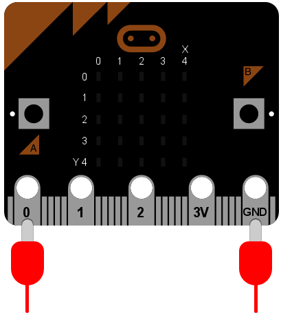
The wire from pin 0 should be attached to the positive connector on the buzzer and the wire from GND to the negative connector.
The following program will cause the buzzer to make a sound:
from microbit import *

pin0.write_digital(1)
This is fun for about 5 seconds and then you’ll want to make the horrible squeaking stop. Let’s improve our example and make the device bleep:
from microbit import *

while True:
    pin0.write_digital(1)
    sleep(20)
    pin0.write_digital(0)
    sleep(480)
Can you work out how this script works? Remember that 1 is “on” and 0 is “off” in the digital world.
The device is put into an infinite loop and immediately switches pin 0 on. This causes the buzzer to emit a beep. While the buzzer is beeping, the device sleeps for twenty milliseconds and then switches pin 0 off. This gives the effect of a short bleep. Finally, the device sleeps for 480 milliseconds before looping back and starting all over again. This means you’ll get two bleeps per second (one every 500 milliseconds).
We’ve made a very simple metronome!
Touch Pins
The simplest example of input via the pins is a check to see if they are touched. So, you can tickle your device to make it laugh like this:
from microbit import *

while True:
    if pin0.is_touched():
        display.show(Image.HAPPY)
    else:
        display.show(Image.SAD)
With one hand, hold your device by the GND pin. Then, with your other hand, touch (or tickle) the 0 (zero) pin. You should see the display change from grumpy to happy!
This is a form of very basic input measurement. However, the fun really starts when you plug in circuits and other devices via the pins.